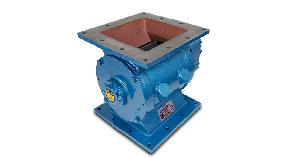
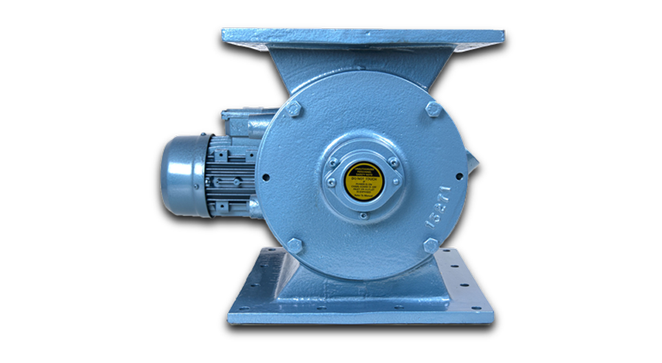
Rotolok introduced a low-cost solution to the dust collector rotary airlock needs. The dust collector rotary airlock is a lighter-duty option for standard dust collection applications.
Constructed with a robust cast iron body and cast iron end covers. Bearings are inboard, and shafts are sealed with lip seals. All valves are direct-driven with a right-angle gearbox and motor.
These valves have been engineered and designed solely as a low-cost alternative for applications with pressure differentials of 3 psi or less. Available in sizes from 6″ to 12″ with round and square inlets.
The general market place covers Cyclones, Bag Houses and Gravity Feed applications with pressures around +/- 3 psi
-
Body
Cast Iron Precision Bored
Standard: Universal flanges to match Square or Circular connections
Heavy Duty: Robust with either Square or Circular flanges -
End Covers
Cast Iron Precision Machined and Spigot Located into Valve Body
-
Rotor
Fabricated Mild Steel Closed (Shrouded) Type Fully Machined
-
Bearings
Ball Type Rigged Inboard Sealed for Life
-
Seal
Shaft Seals Rubber Lip Type
-
Drive
Motorised Worm Box Shaft Mounted on Rotor and Fitted with Standard Nema Motor TEFC 230/460 volt, 3 phase, 60 Hz Flange Mounted to Worm Box
-
Valve Speed
28 RPM on 6″ and 8″ sizes
29 RPM on 10″ and 12″
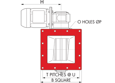
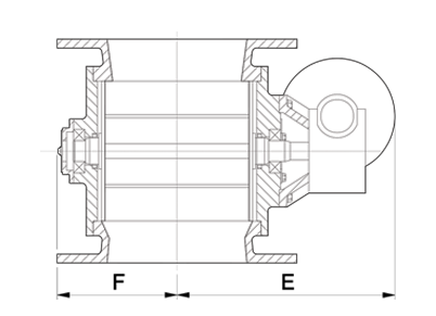
All dimensions are in inches unless otherwise stated
| ROUND DRILLING | SQUARE DRILLING | |||||||||||||||||
|---|---|---|---|---|---|---|---|---|---|---|---|---|---|---|---|---|---|---|
| SIZE | A | C | D | E | F | H | B | O | P | Q | B | O | P | T | U | kW | WEIGHT (lbs) | ft3/rev |
| 6 | 6 | 3/8 | 10 | 12 1/2 | 5 1/2 | 11 3/8 | 11 1/4 | 8 | 7/8 | 9 1/2 | 10 | 12 | 1/2 | 3 | 2 3/4 | 1/2 | 88 | 0.08 |
| 8 | 8 | 1/2 | 12 3/16 | 13 5/8 | 6 5/8 | 11 3/8 | 13 1/2 | 8 | 7/8 | 11 3/4 | 11 13/16 | 12 | 1/2 | 3 | 3 9/16 | 1/2 | 132 | 0.21 |
| 10 | 10 | 1/2 | 15 15/16 | 16 5/16 | 7 13/16 | 13 1/4 | 16 | 12 | 1 | 14 1/4 | 14 3/16 | 12 | 9/16 | 3 | 4 1/4 | 3/4 | 203 | 0.42 |
| 12 | 12 | 9/16 | 18 5/16 | 17 1/2 | 9 | 13 1/4 | 19 1/8 | 12 | 1 | 17 | 17 5/16 | 12 | 11/16 | 3 | 5 1/16 | 3/4 | 317 | 0.75 |
All dimensions are in inches unless otherwise stated
| SIZE | A | B | C | D | E | F | H | O | P | T | U | H/P | WEIGHT (lbs) | ft3/rev |
|---|---|---|---|---|---|---|---|---|---|---|---|---|---|---|
| 6” | 6’’ | 9 ⅞’’ | ½’’ | 11’’ | 11 ⅝’’ | 5 ¾’’ | 14’’ | 12 | ½’’ | 3 | 2 ¾’’ | 1/2 | 152 | 0.08 |
| 8” | 8’’ | 11 ⅞’’ | ⅝’’ | 13’’ | 12 ⅝’’ | 6 ¾’’ | 14’’ | 12 | ½’’ | 3 | 3 ⁹⁄₁₆’’ | 1/2 | 183 | 0.21 |
| 10” | 10’’ | 13 ¼’’ | ⅝’’ | 15’’ | 13 ¹³⁄₁₆’’ | 8’’ | 15’’ | 12 | ⁹⁄₁₆’’ | 3 | 4’’ | 3/4 | 256 | 0.42 |
| 12” | 12’’ | 15 ¾’’ | ½’’ | 18 ⅛’’ | 15 ¼’’ | 9 ⁵⁄₁₆’’ | 15’’ | 12 | ½’’ | 3 | 4 ¹¹⁄₁₆’’ | 3/4 | 386 | 0.75 |
All dimensions are in inches unless otherwise stated
| SIZE | A | B | C | D | E | F | H | O | P | Q | HP | WEIGHT (lbs) | ft3/rev |
|---|---|---|---|---|---|---|---|---|---|---|---|---|---|
| 6’’ | 6’’ | 11 ¼’’ | ½’’ | 10 ⅝’’ | 11 ⅝’’ | 5 ¾’’ | 14’’ | 8 | ⅞’’ | 9 ½’’ | 1/2 | 152 | 0.08 |
| 8’’ | 8’’ | 12 ½’’ | ½’’ | 12 ⅝’’ | 12 ⅝’’ | 6 ¾’’ | 14’’ | 8 | ¹¹⁄₁₆’’ | 11’’ | 1/2 | 183 | 0.21 |
| 10’’ | 10’’ | 14 ½’’ | ⅝’’ | 15’’ | 13 ¹³⁄₁₆’’ | 7 ⅞’’ | 15’’ | 8 | ¹¹⁄₁₆’’ | 12 ⅝’’ | 3/4 | 256 | 0.42 |
| 12’’ | 12’’ | 17 ⅜’’ | ¾’’ | 18 ⅜’’ | 15 ¼’’ | 9 ⁵⁄₁₆’’ | 15’’ | 12 | ⅞’’ | 15 ½’’ | 3/4 | 386 | 0.75 |


